CFFMG Meeting June 2023

Central Florida Furniture Makers Guild

SHAVINGS
Newsletter of the
Central Florida Furniture Makers Guild

Newsletter Editor: Craig Aebli

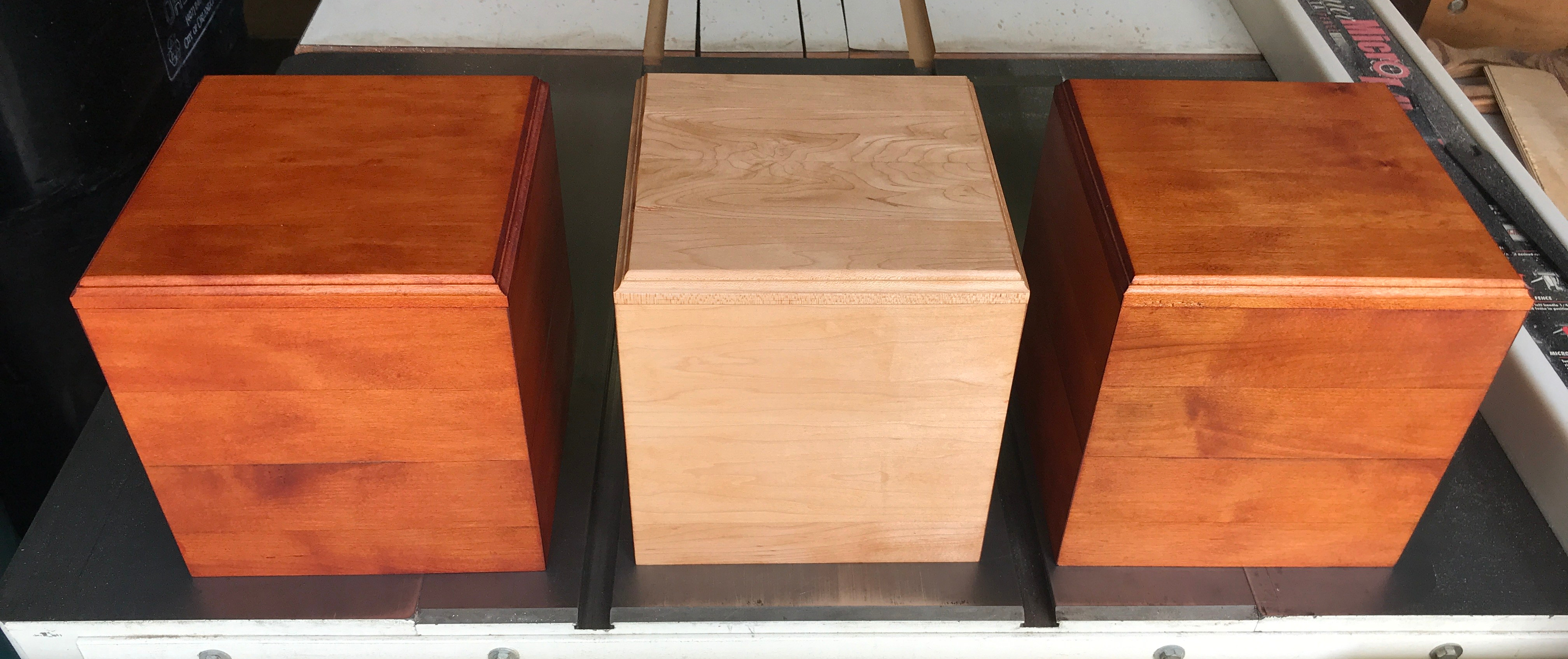
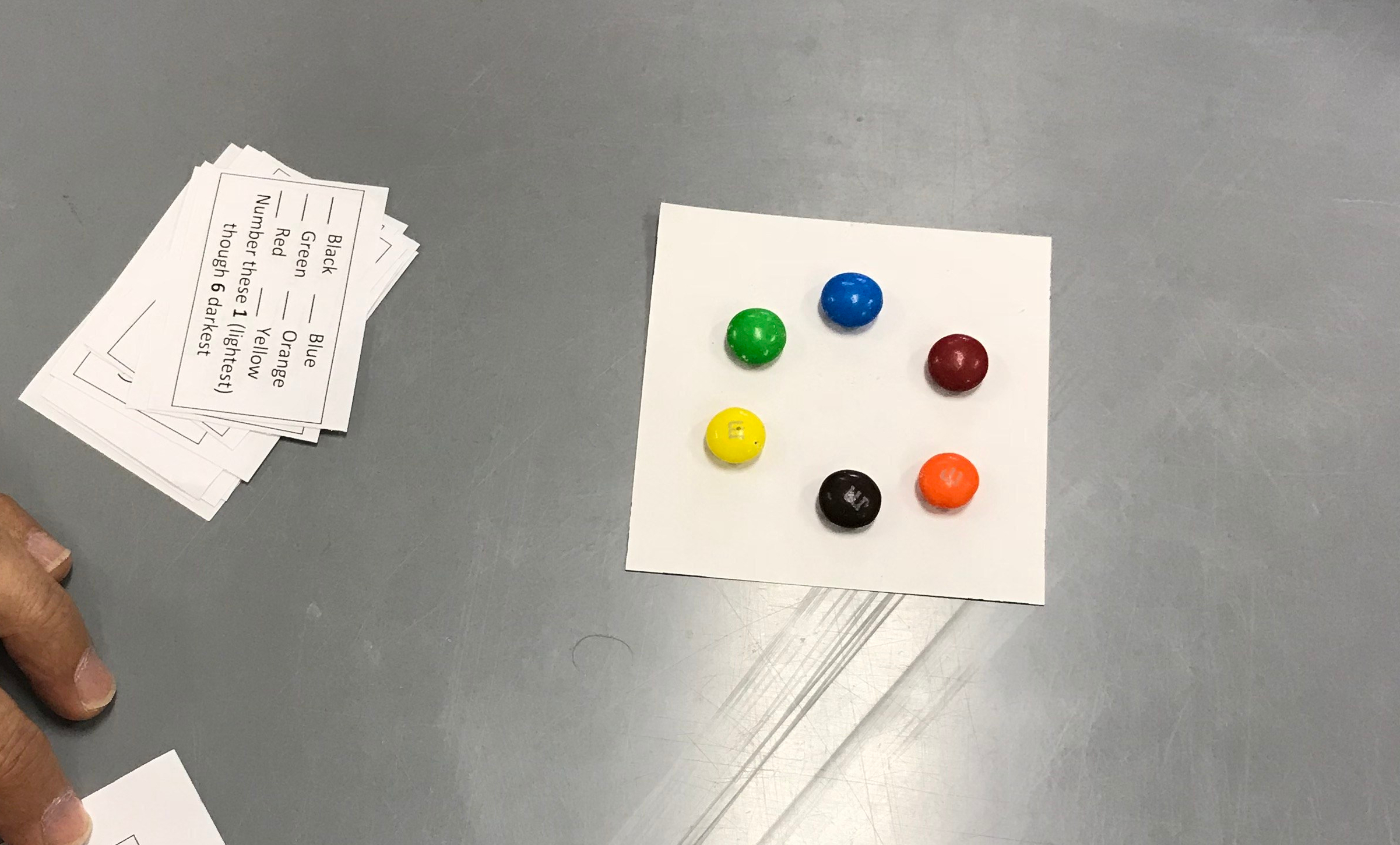
George Poelker did a demonstration of Osmo’s new finish developed for indoor furniture surfaces such as countertops, table tops and cutting boards. It appears to be very waterproof. It  comes out of the bottle white and then dries clear, though there were indications that the white might show on darker woods.

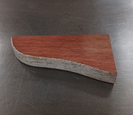
George also showed a piece of teak that he had been given. It was from a chair that had been outside for over 20 years, The weathering appeared to be severe, but when the piece was cut it was obvious the grey weathering was microscopically thin.


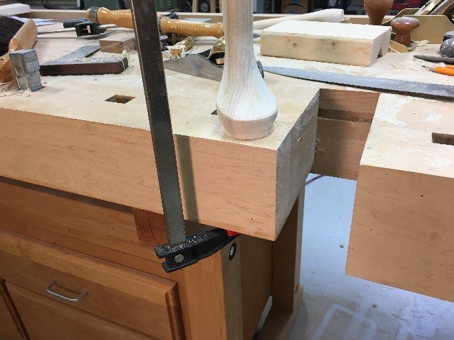
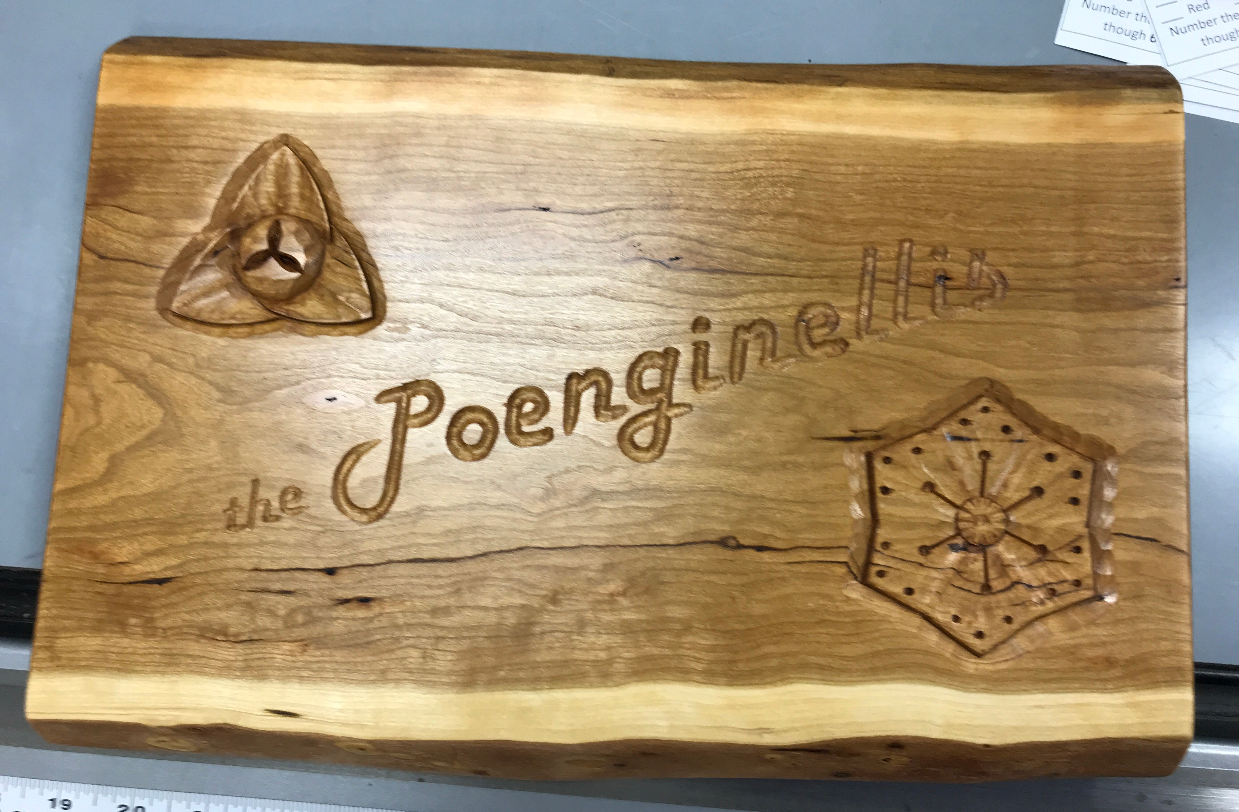
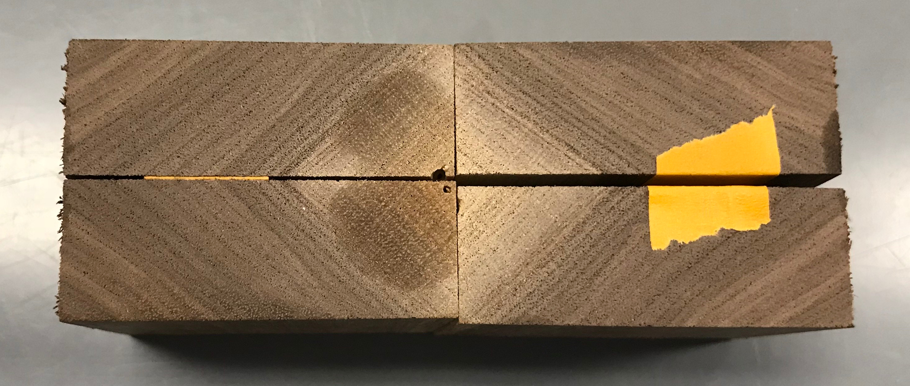
John Kennedy showed a coffee table he had made. It was curved to match a client’s space. He stated that he wasn’t completely satisfied with it because the geometric forms he glued together to make the top had reacted from the moisture in the glue and he needed to pin nail them flat. The pin nail holes became very evident after the finish was applied. Several possible solutions were discussed.
John asked us to guess the wood species of the top. No one guessed correctly. Turns out to be camphor. A discussion on the potential harmful effects of working with camphor ensued.
John also showed a jig he made for drilling holes in sandpaper to fit his ROS.

Pete Savickas showed pictures of some swings he made in remembrance of a friend who recently passed away. The friend had swings and chairs in his front yard where neighbors would gather each evening. The swings Pete made were placed in a neighborhood park.

The swings are entirely of p t 2”x4”’s. The uprights are beveled, and bolted into beveled pockets.  The slats for the seats were ripped 7/8” thick which gave me exact four slats from a 3,1/2”wide board, I use a thin kerf blade.

They were made as a memorial to my friend Jim Koffman who passed away recently .

Pete also showed pictures of a mailbox /flower box combination he made for his yard.

The mailbox/ planter is of a variety of wood scraps with fir as the main post.

Bill Giesey showed pictures of the two desks he has been working on for his grown kids. He showed how he solved the problem of how to run wiring through the desks so it could be hidden and controlled. He made chases out of cheap gutter material he found at a big box store. This solution accomplished all the requirements.

CFFMG Meeting August 2019

Making a Cabriole Leg

Last month, Joe Kunzman demonstrated the process for making a cabriole leg.  His design for the leg is based on the plans for a Queen Anne Hankerchief Table.  The description of the process follows a sequence for the legs of the hankerchief table.  The process begins by preparing the leg blanks.

  •  Mill the stock for your legs.  You will need 4 2-5/8” square billets measuring 27-1/2” long. This is done on a jointer and a planer.  Make sure the corners remain square throughout the milling process.

cabriolelegs1

  • At the top of each billet observed the grain direction. Mark the front corner of each leg perpendicular to the grain, as shown.

 Note: if the front corner is parallel with the grain, then a bullseye pattern will appear on the thigh of the leg which is undesirable.

cabriolelegs2

  • Mark the center point of the billet. Measure off 1/8” toward the front corner.  Dimple with an awl.  Repeat on the opposite side.  Mount in the lathe.  Note: Since this is an offset turn, run the lathe at a slow setting and set your tool rest out from the rear corner.

cabriolelegs3

  •  Turn the pad of the foot. The overall height of the pad is 7/8”. The widest diameter is 2-1/4”. The toe of the pad is 5/16” high by 1-7/8” diameter. Sand while on lathe. Caution: avoid touching the unmachined billet. Draw a pencil mark on the top of the turning for step 1.16.

Lathe tools required:
a. 6 mm ¼” parting tool
b. 10 mm 3/8” finger nail gouge
c. 10 mm 3/8” (or larger) skew

cabriolelegs4

  • The angle and number of mortises varies by leg. All mortises are ¼” wide. Start with the corner leg. Layout 2 mortises on the back of the post. Offset them by 1-1/8” from the back corner on both sides. Cut to a depth of 3/4”. See plan for layout.

cabriolelegs5

  • Continue with the gate leg. It will have a single mortise on the left inside corner, see plan for layout. Offset them by 1-1/8” from the back corner on both sides. Cut to a depth of 3/4”. See plan for layout.

Note: since the rear apron is narrower than the other two, so too will be the length of the mortise.

cabriolelegs6

  • Finish with the two side legs. These legs have one straight mortise and one 45-degree angled mortise.  The mortise positions on each leg are flipped juxtaposed to one another.  See plan for layout.  The angled mortise must be cut with the leg held in v-blocks as shown in the picture.

Caution: Cut the mortises to a depth of 3/4”.  Any deeper and they will be exposed on the opposite side when the post is rounded off in a subsequent step.

cabriolelegs7

  • Using a template, trace the S shape of the leg on two sides of the billet. Position the template so the rear line of post touches the back corner of the billet each time.

Tip: Use a sharp pencil and weights to temporarily hold the template in place while tracing.

cabriolelegs8

  • On the table saw cut line at base of post. The blade should be shy of 1”, leaving a fat 1-5/8” for the post. Repeat on the second side. Make sure the kerf of the blade is on the scrap side of the cut.

cabriolelegs10

  • Cutout the traced pattern on the bandsaw.  Be cautious not to cut into the turned pad or nick the post.

cabriolelegs11

  • Clean up any serious bandsaw marks with a block plane and/or spokeshave on any surface that will not be rounded over in the next 3 steps.

cabriolelegs12

Pencil in quarter and half inch lines from each of the four corners.  These will be used as guides.

cabriolelegs13

  • Shape a chamfer to the quarter inch line using a course rasp on all four corners.  Use V-blocks to clamp the piece in the bench vice.   Do not shape the uncut side of the leg that extend up the back of the post.  In fact, try to stay about an 1/8” away from the top of these, as they will be formed later when the extension blocks are put into place.

cabriolelegs14

  • Round over the chamfer to second line with course and fine rasps.   Cleanup the rasp marks with a card scraper and sandpaper.

cabriolelegs15

  •  Clamp each leg vertically and shape top of pad foot with fine rasp. It’s important to get the front 60-degree arc of the pad flat. Work up to the pencil line drawn in at Step 4.

cabriolelegs16

  • Sand the leg. Shown is a pneumatic 4”x9” sanding drum mounted on the lathe with a 120 grit sleeve. It has been filled with a small amount of air pressure. The speed is set to 500 RPM (slowest speed for this lathe). Some hand sanding will be required in tight areas. The entire process can also be done by hand.

cabriolelegs17

  • Cut out the 2 outside faces of the post on the table saw.  The final dimensions of the post are 1-5/8” square.  Cut from both sides of each post stopping just short of where the saw blade would touch the upper contour of the leg.  A stop block on clamped to the rip fence prevents over cutting.   The rip fence will be used on both sides of the blade.  Finish the cut on the bandsaw.

cabriolelegs18

  • Cleanup the waste and saw marks on the post with a block plane, shoulder plane, and chisel plane.

cabriolelegs19

  • Using a bench chisel and a small file to contour the leg into the post.  Be very careful to not nick the post and maintain a straight crisp line between the leg and post.   Suggest clamping a card scraper to the face of the post to protect it while carving the contour.

cabriolelegs20

  • Trim all the posts to final length.  Use the rip fence and a spacing block to make them all the same length without having to measure each one.

cabriolelegs21

CFFMG Meeting April 2019

We met at Pete’s house.  He did a presentation on how he constructed a Windsor chair.  He based it on the plans from Michael Dunbar (makeawindsor.com) and from his YouTube videos. (Make a sack back windsor) :

SHOW AND TELL

Craig finished his gateleg table.  He used the oil/varnish/mineral spirits mixture first. then shellac.  On the table top, he added a water-based poly from General Finishes.

Bob made a sample sliding dovetail and a cribbage board.

John made a twelve sided vessel using the birds mouth bit from Jack.  He also made a cutting board using a pattern with triangles.

Joe is making a hankerchief table out of poplar as a prototype.  He brought one of the cabriole legs he made.  He used an inflatable sanding drum to sand the leg on his lathe.

Tim made a frame for a stamp he got for his wife.

CFFMG Meeting October 2017

We meet in October at John K.’s house for our annual dinner and show and tell.  After a fabulous dinner prepared by Elizabeth and John, we entered John’s shop to see the latest creations.

John wowed us again with another amazing box.  This time it was a sculpted box made out of walnut.  This box will be donated by John to be used as an auction item to support Alzheimer’s research.

IMG_2549

John also completed another box out of walnut.  It has the inlay design the same as the previous box he made from Sycamore.

Bob S. made some boxes as well.  He used mother of pearl as the inlay material.

Bill G. made some marquetry hibicus flowers as gifts.

IMG_2556

Craig did a practice line and berry stringing design he plans to use for his spice box door.  He used the Lee Valley Veritas inlay tool to do the stringing.


CFFMG Meeting September 2018


Last month we met at Pete’s house.  Next month we will have our annual CFFMG dinner at John’s house.  We decided in January 2019, Craig will host the next meeting.


Bob S. made a mini Moxon vise and showed us the small barrel hinges he uses for boxes.


Bill brought the door from a cabinet he made for his patio.   It’s made out of cedar.


Craig brought the door frame for his spice cabinet.  Scratch stock was used for the beading on the inside of the door frame.


John S. took a class at Marc Adams we they infused dye and resin into wood substrates and made epoxy covered objects and tiles using a variety of techniques.


John K. built a cardboard mockup for a trestle style table he is designing.


John K. is also working on a new box and built a prototype from poplar that he sculpted a wave design into the entire box.  The actual box will be made from walnut.


John K. showed us the sequence of steps he uses for making the checkered board pattern veneered plywood he makes for drawer bottoms and boxes.  It all starts with cutting equal size strips of wood and reorienting them 90 degrees to each other in a series of glue ups to form the checkered pattern.  He maintains the fence position on the table saw to ensure consistent widths of each piece.  After the checkered pattern is complete it is resawn into 1/16th” thick veneer and glued on both sides to 3/32″ plywood.


CFFMG Meeting August 2018 (part 2)

Last month at Joe’s shop we met for a wonderful dinner and CFFMG meeting.  The previous post outlined the program Joe did on making a raised panel door.  Our Show and Tell portion of the meeting is displayed below with all the photos from the meeting.

img_2393.jpg

Joe made this oval fan inlay as his first attempt to prepare for the next SAPFM meeting.  It is made from sandshaded holly and black dyed veneer.


Joe made a couple of urns for veterans.  One of oak with the grain oriented vertically, the other is of cherry that has an angled miter with cove cut into the sides.  He used a panel shaper bit to cut the coves.

img_2395.jpg

Joe got a Jet 18″ bandsaw recently and tried a resaw cut on it without adjusting the guides or changing the blade.

Craig made a miter cutting jig for the bandsaw for cutting miters on boxes.  He used plans from a jig found on woodmagazine.com

https://www.woodmagazine.com/woodworking-plans/jigs/45-degree-miter-sled

IMG_2428

Craig also made boxes for the urns needed for Veteran remains.

IMG_2429

Tim took a drawer making class at Marc Adams.  He had to fit a drawer into a MDF case.

Gary made a photo frame with photos on both sides between two pieces of glass.

John made a pair of wedding boxes for a couple.  Both are made from wenge and curly maple.

IMG_2402

IMG_2403

Here are some additional photos from Joe’s raised panel door presentation.


CFFMG Meeting August 2018

We met at Joe Kunzman’s shop this month.  Joe showed us his method for making raised panel doors using a shaper.  He submitted an outline of the process of which you can see below.

Building a Traditional Raised Panel Door

By Joe Kunzman

Building raised panel doors is something every cabinet maker will need to master.  They are ubiquitous; just look around your house.  Most built-in cabinets and traditional furniture have them.   Using modern techniques, they are straightforward to build. But, you will need a door-making cutter set.   Your choice of cutters will depend on whether you own a router table or a shaper.   I ditched my router table years ago, opting for the more powerful and versatile shaper.   So, that is what you will see in the examples.  Either tool works.

Components of a cabinet door

All raised panel doors are comprised of three components:

  • Stiles – These are the vertical components. Two are required.  They extend the full height of the door.
  • Rails – These are the horizontal components. Two are required.  They fit between the stiles.
  • Panels – This is the field (center) of the door. One is required
  • Additional components can be added if the door is large, or for esthetic reasons.

The rails and stiles form the frame around the panel.  The panel floats in a groove cut into the inside of the rails and stiles.   During assembly, the rails and stile are glued together, but no glue is applied to the panel since it needs to be able to expand and contract freely with seasonal fluctuations in temperature and humidity.

Components of a door cutter set

A basic door cutter set consists of three cutters.

  • A “positive” profile cutter for the inside of all rails and stiles. There are many to choose from.  This cutter will cut the decorative edge visible on the door front and it will cut the groove needed for the door panel
  • A “negative” profile cutter which is the mirror image of the first cutter, above. This cutter is used on the ends of the rails to cut the mating profile.
  • A raised panel cutter. This can be a very large cutter due to the size of most raised panel profiles.  Mine is 5” in diameter.  It can be a bit intimidating when spinning at 12,000 RPM (shaper) or 20,000+ RPM (router).   This is one time you will absolutely want to keep all the safety guards on your machine.   Due to the limitations of some routers, router bit manufacturers have produced raised panel cutters that require the panel be vertical when pushed past the cutter.  This allows them to make the bit smaller and lighter.
  • Some door cutter sets also come with an outside edge profile bit. This bit is used on both the doors and drawer fronts of a cabinet.

  • Sizing the components

    Doors are generally built after the carcass is assembled.  The rough opening of the door opening needs to be measured.  Next, you must decide if your door will be mounted either: flush, full-overlap, or half-overlap to the cabinet face.   Most kitchen cabinets use full-overlap.  Fine furniture is mostly flush or half-overlap.  When overlapping, 1/4″ will need to be added to the face frame’s rough opening dimensions on all sides to arrive at the overall door size.  For double doors, the 1/4″ add-on to the rough opening is applied to both doors taken as a whole.

    I use a simple Excel spreadsheet to calculate all the dimensions.  I input the rough openings, overlap stile and desired width of the rails and stiles.   From there it calculates a cutting list.

    Fabricating the components

    1. Mill the stock to 3/4″ thickness for the stiles and rails, and to 5/8” thickness for the panel. This is what most door cutter sets are designed for.   Rip the rails and stiles to width per the cut list.  Then, crosscut them to length leaving them somewhat oversized.  They will be trimmed flush in later operations.
    2. This thinner dimension of the panel is required because it is set back 1/8” from the rear of these components. This results in the face of the panel flush with the face of the rails and stiles after assembly.   The door panel is then cut to size, per the cut list.
    3. Setup the positive cutter in shaper to profile the inside edges of the rails and stiles. Adjust height of the cutter’s slot segment 1/8” off the shaper table surface. Adjusted the depth of cut for a full reveal of the quarter round, but no more than is needed to maintain the full width of the stock.  (For my positive cutter this was not an option.  To achieve the full quarter-round on profile I had set the depth to remove about 1/8” of stock from the width.  I compensated by ripping the rail stock 1/8” oversize, in the step above.)    Once you are satisfied with your set up, then cut the interior sides of all the rails and stiles.  Cut only one long edge on each.cutter in shaper
    4. Setup the “negative” cutter in the shaper to profile the ends of the rails. Start by cutting two backer boards, used to eliminate tear out.   Both will be made from 3/4″ thick stock ripped to 1”.   The length should approximate the rail length.    Next, cut the “negative” profile into one.

    5.  

      5. A coping sled will be required for cuts at the ends of the rails.  My    homemade coping sled has 2 clamps to hold the sacrificial backer, and 1 clamp to hold the work piece.  With one of the rails mounted in the coping sled, raise the height of the “negative” cutter to match the “positive” profile.  Now you’re ready to make the “backward” cut on the end of each rail.  Use the sacrificial backer board to eliminate tear out.  Adjust the cutter height up or down so that the tongue and groove match.  Cut deep enough that a full tenon is formed.

    6. 6. Switch over to the plain sacrificial backer in the coping sled.  Mount a scrap piece of rail stock in the coping sled and make a cut.  Remove the scrap piece, but do not move the sacrificial backer, as this will be your reference point.  Cut all rails to final length on the table saw.  Mount each rail on the coping sled; aligning the freshly cut end with the end of the sacrificial backer.  This will ensure an exact length.  Make all “forward” cuts with this setup being certain to never move the sacrificial backer from its initial alignment.

    7. Use the raised panel cutter with a bearing on all 4 sides of the panel. This is usually done in several passes, as a lot of material is being removed.   Make sure to cut the end grain first because the resulting tear out will then be cut away when the long grain is cut.   For the final cut, adjust the cutter to form an edge that will fit into the groove cut in the rails and stiles in the prior step.  It should fit snugly (without using force) so the panel doesn’t rattle after assembly.

    8. Assembly

      Prior to assembly, apply stain to the lip of the raised panel that will fit into the groove, since the final finishing will not penetrate this area.   When the panel shrinks, unstained wood will not be exposed.   This is also a good time to sand the inside profiles of the rails and stiles, sand the panel, and seal the end grain of the panels with shellac.

      When assembling the components, only apply glue to the rail ends and the mating areas on the stiles.  Avoid glue touching the panel, it must be allowed to float.   You may have noticed that the panel lip does not contact the bottom of the grooves in the rails and stiles.  This is by design.  Room must be left for expansion.   Clamp the assembly at each end over the rails.   Additional clamping of two temporary braces, to keep the door flat, maybe required.  Check the assembly for squareness by taking diagonal measurements from the rear of the panel at the inside edges of the rails and stiles.  Adjust until they match.  Also, make sure the edges of the rails are perpendicular and not pressed tightly against the panel.


    9. Finishing up

      After the assembly dries trim the door to final size making sure you trim equal amounts from opposite sides.   If the door is a half-overlap, cut a 3/8” by 3/8” rabbit on all rear edges.  Since the door was oversized 1/4″ from the rough opening, the 3/8” rabbit will result in a 1/8” gap between the inside door edge and the rough opening to allow for the hinge hardware and avoid binding when the door is opened.  Some outside edge profile cutters combine the edge profile and rabbit into a single cutting operation.

      A footnote on double doors

      Some doors are made in pairs and installed in face frames with no divider between them.  These are called double doors and allow for a wider opening than a single door.  When making double doors with a full or half overlap, the 1/4″ add-on to the rough opening is applied to both doors taken as a whole.  Said differently, the 1/4″ is not applied to the abutting edges.   Also, if making a partial overlap door, the 3/8” by 3/8” rabbit is not cut into the abutting edges either.

      ———–

      This article was presented to the Central Florida Furniture Makers Guild on August 23, 2018

      © Joe Kunzman, all rights reserved

CFFMG Meeting July 2018

Last month we met at Bob’s shop.  Bob had us answer a perception survey as to lightest to darkest of colored M&M’s.  There was consensus to the lightest (yellow) and the darkest (brown).  The colors in between had some varied answers.  The most answers were for the order of yellow, orange, red, green, blue, and brown.  There was many alternatives to the red, green, and blue order.  It all depended upon how you perceive the colors.IMG_1845

Mike brought a slab of laurel oak, milled from a tree from his yard.  John and Craig tested their moisture meters on the oak and came up with similiar readings.  The readings varied from 8 to 10% up to 12 to 14% depending upon where on the board the meter was placed.  Bob submitted some information regarding the calibration of moisture-meters.

“All meters are calibrated to read the MC of Douglas fir at about 68 
degrees F (The Timber Check is the only exception; it is calibrated for 
red oak).”

“Some meters have built-in species correction (allows you to select a 
wood with the user interface) and some have built-in temperature 
correction.”
“We think that built-in species correction is a feature you can live 
without unless you typically need to take readings on a large quantity 
of wood.”

“A rule of thumb states that the average MC of a board can be found at a 
depth equal to 1/5 to 1/4 the thickness of the board. For example, 
5/16-in. pins are long enough to get an average MC reading on a 
1-1/2-in.-thick board and 1/2-in. pins will work for 2-in. stock.”

“A range of 7 to 20 percent is all you need to check air-dried or 
kiln-dried wood.”
“You can pay extra for a meter with a range that exceeds 30 percent, but 
keep in mind that accurate readings higher than 30 percent are 
impossible because there is just too much water in the wood.”
“At the low end of the MC scale, pin meters are accurate down to 7 
percent and pinless, down to 5 percent.  Readings below these levels are 
unreliable because there is just too little water in the wood.”

img_1878.jpg

Show and Tell 

Bill brought his box with an exceptional marquetry of a tiger on the lid.  The inside was lined with felt.


Pete brought his stool made from pine that was done in the style of Michael Fortune’s table.

IMG_1848

Craig showed a photo of the floating shelves he made for his office.  They are made from 1/4″ maple plywood edged with curly maple.

IMG_1839

John made a plaque for his neighbors.  He carved the national flower of Cambodia (Rumdul) and the state flower of Connecticut (Mountain Laurel) into it.

img_1849.jpg

John K. brought an end grain cutting board he made out of walnut.  He oriented four pieces of sapwood to make the lighter colored diamond shapes.  He then soaked the entire board in mineral oil.  It was glued up with Titebond III.

IMG_1852IMG_1850IMG_1851

John also completed his inlay box with the spring released drawer.

Bob showed his current project of making shelves for his new lumber storage container.  He is gluing up pieces of plywood using new panel clamps from Peachtree Woodworking. He is planing the cauls to camber the ends.

Jay received a present from Bob following his presentation on coopering.

IMG_1890


CFFMG Meeting June 2018

We met at Mike’s shop in June 2018.  Mike showed us how boiling water works well to clean a bandsaw blade, as well as tablesaw blades, when left to soak for about 15 minutes.  He also showed us how to sharpen jointer knives while still on the jointer.  Mike also demonstrated his technique on making mortises and tenons.  He uses a router template with an upcut spiral bit to make the mortise.  He cut the corresponding tenon with a bandsaw and then fit them to size with a rabbitting block plane and a rasp to round the corners.

John K. showed us his latest inlaid box.  He has designed a hidden drawer with a spring release mechanism that is activated by pressing one of the diamond designs on the side of the box.  He made a mockup of the spring released latch.  He purchased a new Woodpecker scribing gauge that assisted him in laying out the inlay designs.

Bob S. carved a basswood cover of rose design for a box lid.  Also showed us the barrel (Soss) hinges he uses.

Pete is making a box for hiding stuff in and turning more ornaments.

Joe is made a coping sled for his shaper and cool electronic controller for his dust collection system.

Craig is making cabinets and shelves for his office.